Although there has been much interest in computational photography within the research and photography communities, progress has been hampered by the lack of a portable, programmable camera with sufficient image quality and computing power. To address this problem, we have designed and implemented an open architecture and application programming interface (API) for such cameras: the Frankencamera. It consists of a base hardware specification, a software stack based on Linux, and an API for C++. Our architecture permits control and synchronization of the sensor and image processing pipeline at the microsecond timescale, as well as the ability to incorporate and synchronize external hardware like lenses and flashes. This paper specifies our architecture and API, and it describes two reference implementations we have built. Using these implementations, we demonstrate several computational photography applications: high dynamic range (HDR) viewfinding and capture, automated acquisition of extended dynamic range panoramas, foveal imaging, and inertial measurement unit (IMU)-based hand shake detection. Our goal is to standardize the architecture and distribute Frankencameras to researchers and students, as a step toward creating a community of photographer-programmers who develop algorithms, applications, and hardware for computational cameras.
1. Introduction
Computational photography refers broadly to sensing strategies and algorithmic techniques that enhance or extend the capabilities of digital photography. Representative techniques include high dynamic range (HDR) imaging, flash/no-flash imaging, coded aperture and coded exposure imaging, panoramic stitching, digital photomontage, and light field imaging.18
Although interest in computational photography has steadily increased among graphics and vision researchers, few of these techniques have found their way into commercial cameras. One reason is that cameras are closed platforms. This makes it hard to incrementally deploy these techniques, or for researchers to test them in the field. Ensuring that these algorithms work robustly is therefore difficult, and so camera manufacturers are reluctant to add them to their products. For example, although HDR imaging has a long history,5,13 the literature has not addressed the question of automatically deciding which exposures to capture, that is, metering for HDR. As another example, while many of the drawbacks of flash photography can be ameliorated using flash/no-flash imaging,7, 15 these techniques produce visible artifacts in many photographic situations.6 Since these features do not exist in actual cameras, there is no strong incentive to address their artifacts.
Particularly frustrating is that even in platforms like smartphones, which encourage app creation and have increasingly capable imaging hardware, the programming interface to the imaging system is highly simplified, mimicking the physical interface of a point-and-shoot camera. This is a logical interface for the manufacturer to include, since it is complete for the purposes of basic camera operations and stable over many device generations. Unfortunately, it means that in these systems it is not possible to create imaging applications that experiment with most areas of computational photography.
To address this problem, we describe a camera architecture and application programming interface (API) flexible enough to implement most of the techniques proposed in the computational photography literature. We believe that the architecture is precise enough that implementations can be built and verified for it, yet high-level enough to allow for evolution of the underlying hardware and portability across camera platforms. Most importantly, we have found it easy to program for.
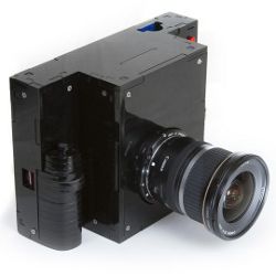
In the following section, we review previous work in this area, which motivates an enumeration of our design goals at the beginning of Section 3. We then describe our camera architecture in more detail. Our two reference implementations are shown in Figure 1. The first is the F2, which is composed of off-the-shelf components mounted in a laser-cut acrylic case. It is designed for extensibility. Our second platform is a Nokia N900 with a custom software stack. While less customizable than the F2, it is smaller, lighter, and readily available in large quantities. It demonstrates that current smartphones often have hardware components with more capabilities than their APIs expose. With these implementations in mind, we describe how to program for our architecture in Section 4. To demonstrate the capabilities of the architecture and API, we show several computational photography applications that cannot easily be implemented on current cameras (Section 5).
2. Prior Work
A digital camera is a complex embedded system, spanning many fields of research. We limit our review of prior work to camera platforms rather than their constituent algorithms, to highlight why we believe a new architecture is needed to advance the field of computational photography.
Although improvements in the features of digital singlelens reflex cameras (DSLRs) have been largely incremental, point-and-shoot camera manufacturers are steadily expanding the range of features available on their cameras. Unfortunately, the camera software cannot be modified, and thus no additional features can be explored by the research community. Software development kits (SDKs) by manufacturers such as Canon and Nikon require tethering the camera to a computer, and provide no more control than the normal user interface.
Though the firmware in these cameras is always proprietary, several groups have successfully reverse-engineered the firmware for some Canon cameras. In particular, the Canon Hack Development Kit4 nondestructively replaces the original firmware on a wide range of Canon point-and-shoot cameras. Photographers can then script the camera, adding features such as custom burst modes, motion-triggered photography, and time-lapse photography. Similarly, the Magic Lantern project12 provides enhanced firmware for Canon 5D Mark II DSLRs. While these projects remove both the need to attach a PC to the camera and the problem of latency, they yield roughly the same level of control as the manufacturer SDKs: the lower levels of the camera are still a black box.
Smartphones are programmable cell phones that allow and even encourage third-party applications. The newest smartphones are capable of capturing still photographs and videos with quality comparable to point-and-shoot cameras. These models contain numerous input and output devices (e.g., touchscreen, audio, buttons, GPS, compass, accelerometers), and are compact and portable. While these systems seem like an ideal platform for a computational camera, they provide limited interfaces to their camera subsystems. Neither Android nor Apple’s iOS devices allow application control over absolute exposure time, or retrieval of raw sensor data—much less the ability to stream full-resolution images at the maximum rate permitted by the sensor. In fact, they typically provide less control of the camera than a DSLR SDK. This lack of control makes these devices useful for only a narrow range of computational photography applications. Despite these limitations, the iPhone app store has several hundred third-party applications that use the camera. This confirms our belief that there is a great interest in extending the capabilities of traditional cameras, an interest we hope to support and encourage with our architecture.
Smart cameras are image sensors combined with local processing, storage, or networking, and are generally used as embedded computer vision systems.3, 22 These cameras provide fairly complete control over the imaging system, with the software stack implementing frame capture, low-level image processing, and vision algorithms such as background subtraction, object detection, or object recognition. Example research systems are the CMUcam,20 Cyclops,16 MeshEye,8 and the Philips wireless smart camera motes.11 Commercial systems include the National Instruments 17XX, Sony XCI-100, and the Basler eXcite series.
The main limitation of these systems is that they are not complete cameras. Most are tethered, few support synchronization with other I/O devices, and none contain a viewfinder or a shutter button. Augmenting these devices with a separate display complicates the system and introduces additional latency.
Our Frankencamera platforms attempt to provide everything needed for a practical computational camera: full access to the imaging system like a smart camera, a full user interface with viewfinder and I/O interfaces like a smartphone, and the ability to be taken outdoors, untethered, like a consumer camera.
3. The Frankencamera Architecture
Informed by our experiences programming for (and teaching with) smartphones, point-and-shoots, and DSLRs, we propose the following set of requirements for a Frankencamera:
- Is handheld, self-powered, and untethered. This lets researchers take the camera outdoors and face real-world photographic problems.
- Has a large viewfinder with a high-quality touchscreen to enable experimentation with camera user interfaces.
- Is easy to program. To that end, it should run a standard operating system, and be programmable using standard languages, libraries, compilers, and debugging tools.
- Has the ability to manipulate sensor, lens, and camera settings on a per-frame basis at video rate, so we can request bursts of images with unique capture parameters for each image.
- Labels each returned frame with the camera settings used for that frame, to allow for proper handling of the data produced by requirement 4.
- Allows access to raw pixel values at the maximum speed permitted by the sensor interface. This means uncompressed, undemosaicked pixels.
- Provides enough processing power in excess of what is required for basic camera operation to allow for the implementation of nearly any computational photography algorithm from the recent literature, and enough memory to store the inputs and outputs (often a burst of full-resolution images).
- Allows standard camera accessories to be used, such as external flash or remote triggers, or more novel devices, such as GPS, inertial measurement units (IMUs), or experimental hardware. It should make synchronizing these devices to image capture straightforward.
Figure 2 illustrates our model of the imaging hardware in the Frankencamera architecture. It is general enough to cover most platforms so that it provides a stable interface to the application designer, yet precise enough to allow for the low-level control needed to achieve our requirements. It encompasses the image sensor, the fixed-function imaging pipeline that deals with the resulting image data, and other photographic devices such as the lens and flash.
One important characteristic of our architecture is that the image sensor is treated as stateless. Instead, it is a pipeline that transforms requests into frames. The requests specify the configuration of the hardware necessary to produce the desired frame. This includes sensor configuration like exposure and gain, imaging processor configuration like output resolution and format, and a list of device actions that should be synchronized to exposure, such as if and when the flash should fire.
The frames produced by the sensor are queued and retrieved asynchronously by the application. Each one includes both the actual configuration used in its capture, and also the request used to generate it. The two may differ when a request could not be achieved by the underlying hardware. Accurate labeling of returned frames (requirement 5) is essential for algorithms that use feedback loops like autofocus and metering.
As the manager of the imaging pipeline, a sensor has a somewhat privileged role in our architecture compared to other devices. Nevertheless, it is straightforward to express multiple-sensor systems. Each sensor has its own internal pipeline and abstract imaging processor (which may be implemented as separate hardware units, or a single time-shared unit). The pipelines can be synchronized or allowed to run independently. Simpler secondary sensors can alternatively be encapsulated as devices (described later), with their triggering encoded as an action slaved to the exposure of the main sensor.
The imaging processor sits between the raw output of the sensor and the application processor, and has two roles. First, it generates useful statistics from the raw image data, including a small number of histograms over programmable regions of the image, and a low-resolution sharpness map to assist with autofocus. These statistics are attached to the corresponding returned frame.
Second, the imaging processor transforms image data into the format requested by the application, by demosaicking, white-balancing, resizing, and gamma correcting as needed. As a minimum we only require two formats: the raw sensor data (requirement 6) and a demosaicked format of the implementation’s choosing. The demosaicked format must be suitable for streaming directly to the platform’s display for use as a viewfinder.
The imaging processor performs both these roles in order to relieve the application processor of essential image processing tasks, allowing application processor time to be spent in the service of more interesting applications (requirement 7). Dedicated imaging processors are able to perform these roles at a fraction of the compute and energy cost of a more general application processor.
Indeed, imaging processors tend to be fixed-functionality for reasons of power efficiency, and so these two statistics and two output formats are the only ones we require in our current architecture. We anticipate that in the longer term image processors will become more programmable, and we look forward to being able to replace these requirements with a programmable set of transformation and reduction stages. On such a platform, for example, one could write a “camera shader” to automatically extract and return feature points and descriptors with each frame to use for alignment, or structure-from-motion applications.
Cameras are much more than an image sensor. They also include a lens, a flash, and other assorted devices. In order to facilitate use of novel or experimental hardware, the requirements that the architecture places on devices are minimal.
Devices are controllable independently of a sensor pipeline by whatever means are appropriate to the device. However, in many applications the timing of device actions must be precisely coordinated with the image sensor to create a successful photograph. The timing of a flash firing in second-curtain sync mode must be accurate to within a millisecond. More demanding computational photography applications, such as coded exposure photography,17 require even tighter timing precision.
To this end, devices may also declare one or more actions that they can take synchronized to exposure. Programmers can then schedule these actions to occur at a given time within an exposure by attaching the action to a frame request. Devices declare the latency of each of their actions, and receive a callback at the scheduled time minus the latency. In this way, any event with a known latency can be accurately scheduled.
Devices may also tag returned frames with metadata describing their state during that frame’s exposure (requirement 5). Tagging is done after frames leave the imaging processor, so this requires devices to keep a log of their recent state.
Some devices generate asynchronous events, such as when a photographer manually zooms a lens, or presses a shutter button. These are time-stamped and placed in an event queue, to be retrieved by the application at its convenience.
While this pipelined architecture is simple, it expresses the key constraints of real camera systems, and it provides fairly complete access to the underlying hardware. Current camera APIs model the hardware in a way that mimics the physical camera interface: the camera is a stateful object, which makes blocking capture requests. This view only allows one active request at a time and reduces the throughput of a camera system to the reciprocal of its latency—a fraction of its peak throughput. Streaming modes, such as those used for electronic viewfinders, typically use a separate interface, and are mutually exclusive with precise frame level control of sensor settings, as camera state becomes ill-defined in a pipelined system. Using our pipelined model of a camera, we can implement our key architecture goals with a straightforward API.
4. Programming the Frankencamera
Developing for a Frankencamera is similar to developing for any Linux device. One writes standard C++ code, compiles it with a cross-compiler, and then copies the resulting binary to the device. Programs can then be run over ssh, or launched directly on the device’s screen. Standard debugging tools such as gdb and strace are available. To create a user interface, one can use any Linux UI toolkit. We typically use Qt and provide code examples written for Qt. OpenGL ES 2.0 is available for hardware-accelerated graphics, and regular POSIX calls can be used for networking, file I/O, synchronization primitives, and so on. If all this seems unsurprising, then that is precisely our aim.
Programmers and photographers interact with our architecture using the “FCam” API. We now describe the API’s basic concepts illustrated by example code.
The four basic concepts of the FCam API are shots, sensors, frames, and devices. We begin with the shot. A shot is a bundle of parameters that completely describes the capture and post-processing of a single output image. A shot specifies sensor parameters such as gain and exposure time (in microseconds). It specifies the desired output resolution, format (raw or demosaicked), and memory location into which to place the image data. It also specifies the configuration of the fixed-function statistics generators by specifying over which regions histograms should be computed and at what resolution a sharpness map should be generated. A shot also specifies the total time between this frame and the next. This must be at least as long as the exposure time and is used to specify frame rate independently of exposure time. Shots specify the set of actions to be taken by devices during their exposure (as a standard STL set). Finally, shots have unique ids auto-generated on construction, which assist in identifying returned frames.
The example code below configures a shot representing a VGA resolution frame, with a 10 ms exposure time, a frame time suitable for running at 30 frames per second, and a single histogram computed over the entire frame:

After creation, a shot can be passed to a sensor in one of the two ways—by capturing it or by streaming it. If a sensor is told to capture a configured shot (by calling sensor.capture(shot)), it pushes that shot into a request queue at the top of the imaging pipeline (Figure 2) and returns immediately.
The sensor manages the entire pipeline in the background. The shot is issued into the pipeline when it reaches the head of the request queue, and the sensor is ready to begin configuring itself for the next frame. If the sensor is ready, but the request queue is empty, then a bubble necessarily enters the pipeline. The sensor cannot simply pause until a shot is available, because it has several other pipeline stages; there may be a frame currently exposing and another currently being read out. Bubbles configure the sensor to use the minimum frame time and exposure time, and the unwanted image data produced by bubbles is silently discarded.
Bubbles in the imaging pipeline represent wasted time and make it difficult to guarantee a constant frame rate for video applications. In these applications, the imaging pipeline must be kept full. To prevent this responsibility from falling on the API user, the sensor can also be told to stream a shot. A shot to be streamed is copied into a holding slot alongside the request queue. Then whenever the request queue is empty, and the sensor is ready for configuration, a copy of the contents of the holding slot enters the pipeline instead of a bubble. Streaming a shot is done using sensor.stream(shot).
Sensors may also capture or stream vectors of shots, or bursts, in the same way that they capture or stream shots. Capturing a burst enqueues those shots at the top of the pipeline in the order given and is useful, for example, to capture a full high-dynamic-range stack in the minimum amount of time. As with a shot, streaming a burst causes the sensor to make an internal copy of that burst, and atomically enqueue all of its constituent shots at the top of the pipeline whenever the sensor is about to become idle. Thus, bursts are atomic—the API will never produce a partial or interrupted burst. The following code makes a burst from two copies of our shot, doubles the exposure of one of them, and then uses the sensor’s stream method to create frames that alternate exposure on a per-frame basis at 30 frames per second. The ability to stream shots with varying parameters at video rate is vital for many computational photography applications, and hence was one of the key requirements of our architecture. It will be heavily exploited by our applications in Section 5.

To update the parameters of a shot or burst that is currently streaming (e.g., to modify the exposure as the result of a metering algorithm), one merely modifies the shot or burst and calls stream again. Since the shot or burst in the internal holding slot is atomically replaced by the new call to stream, no partially updated burst or shot is ever issued into the imaging pipeline.
On the output side, the sensor produces frames, retrieved from a queue of pending frames via the getFrame method. This method is the only blocking call in the core API. A frame contains image data, the output of the statistics generators, the precise time at which the exposure began and ended, the actual parameters used in its capture, and the requested parameters in the form of a copy of the shot used to generate it. If the sensor was unable to achieve the requested parameters (e.g., if the requested frame time was shorter than the requested exposure time), then the actual parameters will reflect the modification made by the system.
Frames can be identified by the id field of their shot. Being able to reliably identify frames is another of the key requirements for our architecture. The following code displays the longer exposure of the two frames specified in the burst above, but uses the shorter of the two to perform metering. The functions displayImage and metering are hypothetical functions that are not part of the API.

In simple programs, it is typically not necessary to check the ids of returned frames, because our API guarantees that exactly one frame comes out per shot requested, in the same order. Frames are never duplicated or dropped entirely. If image data is lost or corrupted due to hardware error, a frame is still returned (possibly with statistics intact), with its image data marked as invalid.
In our API, each device is represented by an object with methods for performing its various functions. Each device may additionally define a set of actions, which are used to synchronize these functions to exposure, and a set of tags representing the metadata attached to returned frames. While the exact list of devices is platform-specific, the API includes abstract base classes that specify the interfaces to the lens and the flash.
The lens can be directly asked to initiate a change to any of its three parameters: focus (measured in diopters), focal length, and aperture, with the methods setFocus, setZoom, and setAperture. These calls return immediately, and the lens starts moving in the background. For cases in which lens movement should be synchronized to exposure, the lens defines three actions to do the same. Each call has an optional second argument that specifies the speed with which the change should occur. Additionally, each parameter can be queried to see if it is currently changing, what its bounds are, and its current value. The following code moves the lens from its current position to infinity focus over the course of 2s.

A lens tags each returned frame with the state of each of its three parameters during that frame. Tags can be retrieved from a frame like so:

The flash has a single method that tells it to fire with a specified brightness and duration, and a single action that does the same. It also has methods to query bounds on brightness and duration. Flashes with more capabilities (such as the strobing flash in Figure 3) can be implemented as subclasses of the base flash class. The flash tags each returned frame with its state, indicating whether it fired during that frame, and if so with what parameters.
The following code example adds an action to our shot to fire the flash briefly at the end of the exposure (second-curtain sync). The results of a similar code snippet run on the F2 can be seen in Figure 3.

Other devices can be straightforwardly incorporated into the API, allowing easy management of the timing of their actions. One merely needs to inherit from the Device base class, add methods to control the device in question, and then define any appropriate actions, tags, and events. This flexibility is critical for computational photography, in which it is common to experiment with novel hardware that affects image capture.
In our current API implementations, apart from fixed-function image processing, FCam runs entirely on the ARM CPU in the OMAP3430, using a small collection of user-space threads and modified Linux kernel modules. Our system is built on top of Video for Linux 2 (V4L2)—the standard Linux kernel video API. V4L2 treats the sensor as stateful with no guarantees about timing of parameter changes. To provide the illusion of a stateless sensor processing stateful shots, we use several real-time-priority threads to manage updates to image sensor parameters, readback of image data and metadata, and device actions synchronized to exposure.
Our image sensor drivers are standard V4L2 sensor drivers with one important addition. We add controls to specify the time taken by each individual frame, which are implemented by adjusting the amount of extra vertical blanking in sensor readout.
Our goals for the API were to provide intuitive mechanisms to precisely manipulate camera hardware state over time, including control of the sensor, fixed-function processing, lens, flash, and any associated devices. We have accomplished this in a minimally surprising manner, which should be a key design goal of any API. The API is limited in scope to what it does well, so that programmers can continue to use their favorite image processing library, UI toolkit, file I/O, and so on. Nonetheless, we have taken a “batteries included” approach, and made available control algorithms for metering and focus, image processing functions to create raw and JPEG files, and example applications that demonstrate using our API with the Qt UI toolkit and OpenGL ES.
Implementing the API on our two platforms required a shadow pipeline of in-flight shots, managed by a collection of threads, to fulfill our architecture specification. This makes our implementation brittle in two respects. First, an accurate timing model of image sensor and imaging processor operation is required to correctly associate output frames with the shot that generated them. Second, deterministic guarantees from the image sensor about the latency of parameter changes are required, so that we can configure the sensor correctly. In practice, there is a narrow time window in each frame during which sensor settings may be adjusted safely. To allow us to implement our API more robustly, future image sensors should provide a means to identify every frame they produce on both the input and output sides. Setting changes could then be requested to take effect for a named future frame. This would substantially reduce the timing requirements on sensor configuration. Image sensors could then return images tagged with their frame id (or even the entire sensor state), to make association of image data with sensor state trivial.
5. Applications
We now describe a number of applications of the Frankencamera architecture and API to concrete problems in photography. Most run on either the N900 or the F2, though some require hardware specific to one platform or the other. These applications are representative of the types of in-camera computational photography our architecture enables, and several are also novel applications in their own right. They are all either difficult or impossible to implement on existing platforms, yet simple to implement under the Frankencamera architecture.
Long-exposure photos taken without use of a tripod are usually blurry, due to natural hand shake. However, hand shake varies over time, and a photographer can get “lucky” and record a sharp photo if the exposure occurs during a period of stillness (Figure 4). Our “Lucky Imaging” application uses an experimental Nokia three-axis gyroscope affixed to the front of the N900 to detect hand shake. Utilizing a gyroscope to determine hand shake is computationally cheaper than analyzing full resolution image data, and will not confuse blur caused by object motion in the scene with blur caused by hand shake. We use an external gyroscope because the internal accelerometer in the N900 is not sufficiently accurate for this task.
To use the gyroscope with the FCam API, we created a device subclass representing a three-axis gyroscope. The gyroscope object then tags frames with the IMU measurements recorded during the image exposure. The application streams full-resolution raw frames, saving them to storage only when their gyroscope tags indicate low motion during the frame in question. The ease with which this external device could be incorporated is one of the key strengths of our architecture.
This technique can be extended to longer exposure times where capturing a “lucky image” on its own becomes very unlikely. Indeed, Joshi et al.9 show how to deblur the captured images using the motion path (as recorded by the IMU) as a prior.
CMOS image sensors are typically bandwidth-limited devices that can expose pixels faster than they can be read out into memory. Full-sensor-resolution images can only be read out at a limited frame rate: roughly 12 fps on our platforms. Low-resolution images, produced by downsampling or cropping on the sensor, can be read at a higher-rate: up to 90 fps on the F2. Given that we have a limited pixel budget, it makes sense to only capture those pixels that are useful measurements of the scene. In particular, image regions that are out-of-focus or oversaturated can safely be recorded at low spatial resolution, and image regions that do not change over time can safely be recorded at low temporal resolution.
Foveal imaging uses a streaming burst, containing shots that alternate between downsampling and cropping on the sensor. The downsampled view provides a 640 x 480 view of the entire scene, and the cropped view provides a 640 x 480 inset of one portion of the scene, analogously to the human fovea (Figure 5). The fovea can be placed on the center of the scene, moved around at random in order to capture texture samples, or programmed to preferentially sample sharp, moving, or well-exposed regions. For now, we have focused on acquiring the data, and present results produced by moving the fovea along a prescribed path. In the future, we intend to use this data to synthesize full-resolution high-framerate video, similar to the work of Bhat et al.2
Downsampling and cropping on the sensor is a capability of the Aptina sensor in the F2 not exposed by the base API. To access this, we use derived versions of the Sensor, Shot, and Frame classes specific to the F2 API implementation. These extensions live in a sub-namespace of the FCam API. In general, this is how FCam handles platform-specific extensions.
 5.3. HDR viewfinding and capture
HDR photography operates by taking several photographs and merging them into a single image that better captures the range of intensities of the scene.19 While modern cameras include a “bracket mode” for taking a set of photos separated by a preset number of stops, they do not include a complete “HDR mode” that provides automatic metering, viewfinding, and compositing of HDR shots. We use the FCam API to implement such an application on the F2 and N900 platforms.
HDR metering and viewfinding is done by streaming a burst of three 640 x 480 shots, whose exposure times are adjusted based on the scene content, in a manner similar to Kang et al.10 The HDR metering algorithm sets the long-exposure frame to capture the shadows, the short exposure to capture the highlights, and the middle exposure as the midpoint of the two. As the burst is streamed by the sensor, the three most recently captured images are merged into an HDR image, globally tone-mapped with a gamma curve, and displayed in the viewfinder in real time. This allows the photographer to view the full dynamic range that will be recorded in the final capture, assisting in composing the photograph.
Once it is composed, a high-quality HDR image is captured by creating a burst of three full-resolution shots, with exposure and gain parameters copied from the viewfinder burst. The shots are captured by the sensor, and the resulting frames are aligned and then merged into a final image using the Exposure Fusion algorithm.14 Figure 6 shows the captured images and results produced by our N900 implementation.
The field of view of a regular camera can be extended by capturing several overlapping images of a scene and stitching them into a single panoramic image. However, the process of capturing individual images is time-consuming and prone to errors, as the photographer needs to ensure that all areas of the scene are covered. This is difficult since panoramas are traditionally stitched off-camera, so that no on-line preview of this capture process is available.
In order to address these issues, we implemented an application for capturing and generating panoramas using the FCam API on the N900. In the capture interface, the viewfinder alignment algorithm1 tracks the position of the current viewfinder frame with respect to the previously captured images, and a new high-resolution image is automatically captured when the camera points to an area that contains enough new scene content. A map showing the relative positions of the previously captured images and the current camera pose guides the user in moving the camera (top left of Figure 7). Once the user has covered the desired field of view, the images are stitched into a panorama in-camera, and the result can be viewed for immediate assessment.
In addition to in-camera stitching, we can use the FCam API’s ability to individually set the exposure time for each shot to create a panorama with extended dynamic range, in the manner of Wilburn et al.21 In this mode, the exposure time of the captured frames alternates between short and long, and the amount of overlap between successive frames is increased, so that each region of the scene is imaged by at least one short-exposure frame and at least one long-exposure frame. In the stitching phase, the long and short exposure panoramas are generated separately, then combined14 to create an extended dynamic range result.
6. Conclusion
We have described the Frankencamera—a camera architecture suitable for experimentation in computational photography, and two implementations: our custom-built F2, and a Nokia N900 running the Frankencamera software stack. Our architecture includes an API that encapsulates camera state in the shots and frames that flow through the imaging pipeline, rather than in the photographic devices that make up the camera. By doing so, we unlock the underexploited potential of commonly available imaging hardware. The applications we have explored thus far are low-level photographic ones. With this platform, we now plan to explore applications in augmented reality, camera user interfaces, and augmenting photography using online services and photo galleries.
The central goal of this project is to enable research in computational photography. We are therefore distributing our platforms to students in computational photography courses, and are eager to see what will emerge. In the longer term, our hope is that consumer cameras and devices will become programmable along the lines of what we have described, enabling exciting new research and creating a vibrant community of programmer-photographers.
Acknowledgments
For this work, A. Adams was supported by a Reed-Hodgson Stanford Graduate Fellowship; E.-V. Talvala was supported by a Kodak Fellowship. S.H. Park and J. Baek acknowledge support by Nokia. D. Jacobs received support from a Hewlett Packard Fellowship, and J. Dolson received support from an NDSEG Graduate Fellowship from the United States Department of Defense. D. Vaquero was an intern at Nokia during this work. This work was partially done while W. Matusik was a Senior Research Scientist and B. Ajdin was an intern at Adobe Systems, Inc., and we thank David Salesin and the Advanced Technology Labs for support and feedback. Finally, M. Levoy acknowledges support from the National Science Foundation under award 0540872.
Figures
 Figure 1. Two implementations of the Frankencamera architecture: The custom-built F2 (left)—portable and self-powered, best for projects requiring flexible hardware; and the Nokia N900 (right) with a modified software stack—a compact commodity platform best for rapid development and deployment of applications to a large audience.
 Figure 2. The Frankencamera abstract architecture. The architecture consists of an application processor, a set of photographic devices such as flashes or lenses, and one or more image sensors, each with a specialized image processor. A key aspect of this system is that image sensors are pipelined. The architecture does not dictate the number of stages; here we show a typical system with four frames in flight at a time.
 Figure 3. The Frankencamera API provides precise timing control of secondary devices like the flash. Here, two Canon flash units were mounted on an F2, one set to strobe and one to fire once at end of the exposure.
 Figure 4. Lucky Imaging. An image stream and three-axis gyroscope data for a burst of three images with 0.5s exposure times. The FCam API synchronizes the image and motion data, and only the frames determined to have low motion are saved to storage.
 Figure 5. Foveal imaging records a video stream that alternates between a downsampled view of the whole scene and full-detail insets of a small region of interest. In this example, the inset is set to scan over the scene, the region of interest moving slightly between each pair of inset frames.
 Figure 6. HDR imaging. The high-speed capture capabilities of FCam allow capturing a burst of frames for handheld HDR with minimal scene motion. The final composite produced on-device is on the right.
 Figure 7. Extended dynamic range panorama capture. A Frankencamera platform allows for experimentation with novel capture interfaces and camera modes. Here we show a semiautomated panorama capture program, which produces an extended dynamic range panorama.


Join the Discussion (0)
Become a Member or Sign In to Post a Comment