The cameras in our phones and tablets have turned us all into avid photographers, regularly using them to capture special moments and document our lives. One notable feature of camera phones is they are compact and fully automatic, enabling us to point and shoot without having to adjust any settings. However, when we need to capture photos of high aesthetic quality, we resort to more sophisticated DSLR cameras in which a variety of lenses and flashes can be used interchangeably. This flexibility is important for spanning the entire range of real-world imaging scenarios, while enabling us to be more creative.
Key Insights
- Cambits includes a set of physical blocks for building computational cameras with multiple functionalities, including high dynamic range, wide angle, panoramic, collage, kaleidoscopic, post-focus, light field, stereo imaging, and even a microscope.
- Blocks include sensors, actuators, lenses, optical attachments, and light sources attached through magnets without screws or cables.
- The configuration of the blocks can be changed without rebooting any of the related hardware or software.
Many developers have sought to make these cameras even more flexible through both hardware and software. For example, Ricoh’s GXR camera has interchangeable lens units, each with a different type of sensor.12 Some manufacturers make their cameras more flexible through application program interfaces (APIs) developers then use to control various camera parameters and create new image-processing tools. For example, Olympus’s Open Platform Camera, released in 2015, can be controlled via Wi-Fi and Bluetooth.8 And at the high-performance end of the camera market, RED offers a modular camera with interchangeable parts, including lenses, battery packs, and broadcast modules.10 Although they provide some level of flexibility, such cameras are limited in the types and quality of images they are actually able to produce.
In the realm of research, Adams et al.1 proposed a computational photography platform called Frankencamera, including API, sensor interface, and image-processing unit. That system can be used to implement various computational-imaging methods. However, its hardware is relatively rigid, limiting the extent to which it can be reconfigured. Manakov et al.5 proposed a camera system that can accommodate different optical addons, including kaleidoscope-like imaging to make optical copies of the captured image. Different filters are then used to produce high dynamic range (HDR), multispectral, polarization, and light-field images. The system provides some reconfigurability but is bulky and difficult to scale in terms of functionality. Finally, reconfigurability is a well-explored topic in the field of science education;16 for instance, Schweikardt and Gross14 developed a related robot kit, including blocks with multiple functionalities they call Cublets. And littleBits Electronics Inc. developed a modular electronic system for experiential learning in which the modules can be snapped together through a magnetic interface to create circuits with various functionalities.4

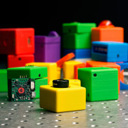
Figure. Cambit pieces can be assembled to create a dozen different imaging systems. To celebrate this assortment, Communications has published four different covers, each one featuring a different Cambit configuration.
Here, we present Cambits, a set of physical blocks that can be used to build a variety of cameras with different functionalities. Blocks include sensors, actuators, lenses, optical attachments, and light sources, assembled with magnets without screws or cables. When two blocks are attached, they are connected electrically through spring-loaded pins that carry power, data, and control signals. The host computer always knows the current configuration and automatically provides a menu of imaging functionalities from which the user can choose. Cambits is a scalable system, allowing users to add new blocks and computational photography algorithms to the current set.
Concept
Figure 1a shows the set of blocks that make up Cambits. They come in a variety of colors, each indicating a specific function: white for base, red for image sensor, blue for flash, green for actuators and spacers, yellow for lenses, and orange and purple for optical attachments. Figure 1b shows the host computer, which always knows the current Cambits configuration, using a suite of computational photography algorithms to produce a variety of images. The system reflects a number of attributes:
Ease of assembly. The blocks are attached using magnets, and the configuration of blocks can be changed without requiring a reboot of the hardware or software;
Self-identification. The host computer can detect the system’s current configuration, information that is conveyed to the user through 3D visualization and a menu of functionalities it can perform;
Diverse functionality. Since there are many types of blocks, many controllable by the user, a diverse set of camera systems can be configured in which each is able to produce a different type of image; and
Scalability. The design of the system’s hardware and software architecture makes it inherently scalable so new blocks and computational photography algorithms are added readily to the existing set.

Figure 1. Cambits overview: (a) Cambits components; (b) a Cambits configuration, with host computer displaying a 3D visualization of the current configuration and a menu of functionalities it can perform; and (c) Cambits blocks and their specifications.
System Architecture
A number of Cambits attributes follow the design of the Cambits hardware and software architecture:
Mechanical and electrical connections. Each Cambits block is 40mm along at least two of its three dimensions. We 3D printed the chassis of each block, including sockets close to its corners designed to hold magnets; the magnets are used to attach blocks to each other, as well as to mechanically align them, as in Figure 2a; the alignment is aided by convex and concave bumps on the surface of the chassis. The polarities of the magnets in each block are also chosen such that it is not possible for the user to attach two blocks that are otherwise incompatible. For instance, a lens block cannot be directly attached to an actuator block. When two blocks are attached, a set of either four or six spring-loaded pins on one block (see Figure 2b) is aligned and electrically connected to contact pads on the other block. The system uses USB 2.0 for the data signal and I2C for the control signal.

Figure 2. Cambits detachable connector: (a) mechanical assembly and alignment of blocks using magnets; and (b) electrical connection between blocks using spring-loaded pins that carry power, data, and control signals.
Tree structure with bucket brigade. Each Cambits block has three types of pins for conveying power, data signals, and control signals. The data signal conveys image data from the sensor block. The control signal conveys the configuration data upstream and various commands (such as the actuator block’s rotation parameters and the flash’s strobing parameters) downstream.
Cambits is a scalable system, allowing users to add new blocks and computational photography algorithms to the existing set.
These signals communicate through a tree structure. The host device—the root of the Cambits structure—provides electrical power to all blocks in the configuration, detects the current configuration of the entire tree structure, and controls all blocks within the tree. This design ensures each block is able to connect with multiple other blocks. Upstream is defined as the direction toward the host device and downstream as the direction in which components proceed forward from the host device (see Figure 3).

Figure 3. Tree architecture used to implement Cambits; power flows downstream, data flows upstream, and control signals are communicated in bucket-brigade fashion.
The data signal flows upstream directly from each sensor block to the host device. However, the control signals are passed from component to component in bucket-brigade fashion. Each block is able to communicate through control signals with only the blocks that are connected to it. When a block is attached to the system, it scans the components downstream. If it detects any blocks, it reads the configuration data of the blocks that are downstream, adds its own identity and address to the data, and then sends the information upstream. As a result, the host device is able to detect the complete order of the configuration. If we had instead used a conventional electrical bus for the control signals, the system would not have been able to detect the order of the blocks. Moreover, a conventional bus would not be able to detect configurations in which multiple blocks have the same address, as is possible when using the I2C interface.
When the host device seeks to control a specific block in the tree structure, it sends its command and the address of the block to the base block. The base block and subsequent blocks pass the command downstream in bucket-brigade fashion. The addressed block ultimately receives the command and executes it.
Controller board. A key aspect of the design is the controller board inside the base, actuator, spacer, and sensor blocks. It includes a microcontroller unit (MCU) (Texas Instruments MSP430F5510) with two serial ports for the bucket brigade. The controller board has an upstream interface and a downstream interface (see Figure 4).

Figure 4. The base, actuator, spacer, and sensor blocks include a controller board that allows a block to communicate with its adjacent blocks.
When a block with the controller is attached to the system, it turns on automatically, thus triggering the firmware on its MCU to start scanning downstream for approximately 100msec to communicate with its adjacent blocks. When the block is removed from the system, it loses power, and the firmware stops.
Each block has a power circuit to prevent inrush current and voltage drop when attached, thus maintaining a steady input voltage. Due to the circuit, the system can be reconfigured without requiring a reboot of the hardware (blocks) or the software running on the host computer.
The controller board can also control other devices (such as the servo motor in the actuator block and the LED controller in the flash block) through the I2C bus, pulse-width modulation (PWM), and general-purpose input outputs (GPIO) based on commands it receives from the host device. For example, when an actuator block receives the command for rotation, the MCU generates the pulse signal needed to drive its servo motor.
The I2C interface is also useful in terms of scalability because it is widely used in the field of embedded systems, allowing us to add various extra devices (such as a light sensor, acoustic sensor, IR sensor, GPS, IMU, and multispectral light source) to the Cambits set.
Lens blocks and optical attachments. The lens block includes an identification board with I2C expander device that can detect the identification number of the lens type itself and an additional optical attachment connected to the lens (such as soft focus filter, lens array, and “teleidoscope,” or lens for creating kaleidoscope-like images). The optical attachment includes no electrical parts but does have up to three bumps that push against mechanical switches on the lens block to generate a three-bit code the lens block can use to identify the attachment. The lens block then sends this information upstream.
Sensor block. The sensor block includes a Point Grey camera board (BFLY-U3-13S2C-CS) that can produce 1.3-megapixel video in various formats (such as YUV411 and RGB8) and send the video upstream as a USB 2.0 data signal. In designing Cambits, we aimed to minimize the length of the data signal line and the number of connectors so as to enable high-frequency (480Mbps) transmission needed to preserve the integrity of the video.15 Users are able to control various imaging parameters of the sensor board (such as exposure time and gain) from the host device.
Mechanical design. As mentioned, the Cambits blocks attach to each other through magnets invisible to the user, as they are embedded within the plastic (polylactic acid, or PLA) enclosing the blocks. To ensure the magnetic forces exerted through the PLA block enclosures are strong enough to keep the blocks attached, we used Neodymium block magnets in dimensions 3/8″ × 1/4″ × 1/16″. To ensure precise optical alignment between blocks, we designed the faces of the block covers with small mechanical bumps and indentations. The dimensions of the PLA enclosures of the blocks must be precise enough to ensure that when lens and optical attachment blocks are attached to a sensor block, an image is achieved with the desired depth of field. Finally, as in Figure 4, the controller circuit board within each block includes not only the various electronic components but also the spring-loaded connectors used to electrically connect the block to the one to which it is attached. In our prototype, the PLA enclosure, magnets, and controller circuit board add approximately 5.2mm in linear dimension to the component—sensor, actuator, and flash—in a block. Detailed mechanical design files are available at http://www.cs.columbia.edu/CAVE/projects/cambits.
Software. The software system that runs on the host device captures images from the Cambits system, giving users a 3D visualization of the current configuration and the option to apply various computational photography methods to the captured images. The current implementation runs on Windows and is based on open source libraries (such as Open CV-v2.4.10 and Cinder v1.20) (see Figure 5). It also uses the Point Grey Fly-capture2 software interface to control the image sensors.

Figure 5. Cambits software architecture.
The Cambits API is also able to receive images from the Point Grey SDK and control camera parameters (such as exposure time and gain) and various devices on the tree architecture, including servo motors, linear actuators, and LEDs, through serial ports. The API and the open libraries allow developers to add new blocks and image-processing algorithms to the system.
Functionality
We have used Cambits to assemble a range of computational cameras (see Figure 6). To construct a basic one, we use a base, a sensor block, and 8mm lens block. In HDR mode, the camera captures six images with different exposure times—where the exposures are the geometric sequence t, 2t, 4t, 8t, 16t, and 32t seconds—computes an HDR image using a triangular weighting function,2 and then “tone maps” it using Reinhard’s algorithm.11

Figure 6. Example results; for high-resolution versions, see http://www.cs.columbia.edu/CAVE/projects/cambits/.
Users can also move this basic camera around to capture a set of images that can be fused to obtain a scene collage. The system is able to detect the features in each image using the scale-invariant feature transform (SIFT) algorithm, reduce the outliers using the random sample consensus (RANSAC) algorithm, and find corresponding features between pairs of images. Cambits uses the image with the most corresponding features, with all remaining images as the center image of the collage, transforming the remaining images to align with the center image and overlay to obtain the collage.7
Cambits also includes a variety of lenses. For instance, a fisheye lens with a focal length of 1.3mm and f-number of 2.8 can be used to capture a wide-angle image of a scene with horizontal field of view of 180 degrees. Since the host computer knows the type of lens being used, the software automatically maps the captured image to a perspective without barrel distortion.13
As with the lenses, users can attach a variety of optical filters to the lens of the imaging system, including simple optical filters like diffusion and polarization, as well as more complex ones (such as a lens array and a teleidoscope). The Cambits lens-array attachment includes seven acrylic ball lenses to produce a 4D light-field image of the scene.3 The teleidoscope attachment produces a kaleidoscope image. An acrylic ball lens in front of the attachment captures the scene image, and a set of first-surface planar mirrors between the ball lens and the lens block creates multiple rotated copies of the image.
The focal stack lens block includes a linear actuator that physically sweeps the lens to capture a set of images corresponding to different focus settings. The linear actuator moves the lens in steps of 0.05mm, with a total travel distance up to 2.0mm, using a piezoelectric linear actuator to move the lens precisely. The captured stack of images helps compute an index map that represents the image in which each pixel is focused. The focal stack lens block then generates an interactive image that lets users click on any part of the image to bring it into focus.6,17
We designed Cambits so it would be possible to insert a rotary actuator between the base and the sensor to scan a panorama of a scene. If the camera is rotated off-axis—with an offset between the rotation axis and the center of projection of the camera—users would be able to take left and right image strips from the captured sequence of images to generate a stereo panorama for creating virtual reality.9 In the example in Figure 6g, 120 images were taken while the actuator rotated 120 degrees and the offset between the rotation axis and the center of projection of the camera lens was 70mm.
A second rotary actuator can be added to the system to configure a pan/tilt camera system.
Cambits is not limited to a single image sensor. Its second base can be used with two sensor blocks and lenses to create a stereo camera system with a baseline of 44mm. Cambits processes the left and right video streams from this system in real time to produce a gray-coded-depth video of the scene.
Cambits can also be used to assemble a microscope that includes an objective lens, a mechanism to adjust the height of the sample slide to bring the sample into focus, and an LED light to “bright field” illuminate the sample. The user controls the LED in terms of brightness through the host computer. Alternatively, ambient illumination in the environment can be used to backlight the sample.
Conclusion
Cambits is a versatile modular imaging system that lets users create a range of computational cameras. The current prototype is a proof of concept we use to demonstrate key aspects of Cambits: ease of assembly, self-identification, and diverse functionality. We have thus shown Cambits can be a powerful platform for computational photography, enabling users to express their creativity along several dimensions. An important aspect of Cambits is that it is designed to be an open platform that is scalable. That design allows users to add multiple hardware blocks, including structured light sources, multispectral sources, telescopic optical attachments, and even non-imaging sensors for measuring acceleration, orientation, sound, temperature, and pressure. We anticipate developing algorithms that use such a diverse set of sensors to trigger/control various image-capture-and-processing strategies. To encourage others to modify or build on the current system, we have made the details of its hardware and software design available at http://www.cs.columbia.edu/CAVE/projects/cambits/databases/cambits_supporting_database.zip.
Acknowledgments
We did this research at the Computer Vision Laboratory of Columbia University in New York while Makoto Odamaki was a Visiting Scientist from Ricoh Company, Ltd.; for the design data covered here, see http://www.cs.columbia.edu/CAVE/projects/cambits. We thank William Miller for designing and 3D printing the chassis of the Cambits blocks, Wentao Jiang for his contribution to the user interface, and Daniel Sims for editing the demonstration video and formatting the project webpage. Divyansh Agarwal, Ethan Benjamin, Jihan Li, Shengyi Lin, and Avinash Nair implemented several of the computational-photography algorithms. The authors also thank Anne Fleming for proofreading an early draft of the article.

|
Figure. Watch the authors discuss their work in this exclusive Communications video. https://cacm.acm.org/videos/cambits |


Join the Discussion (0)
Become a Member or Sign In to Post a Comment